By Carroll Marston, Sales and Engineering, ACE Clamps
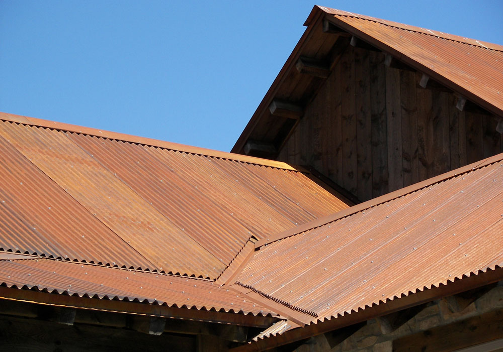
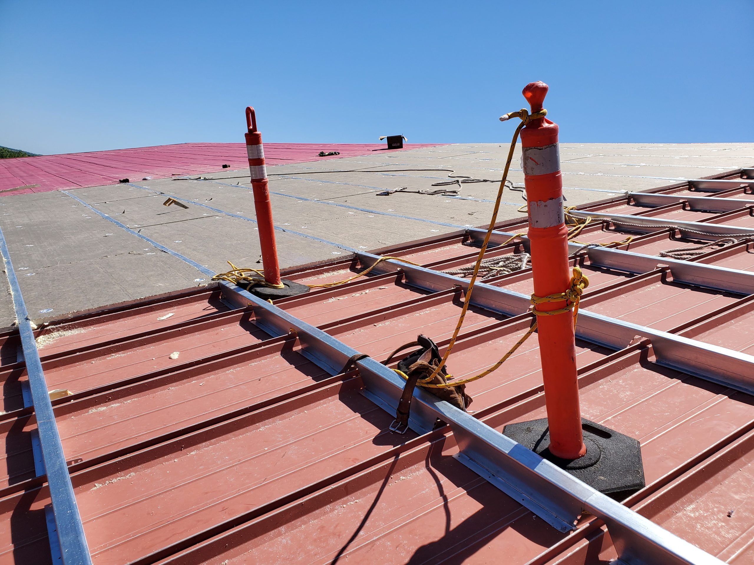
Standing seam metal roofs are an ideal roofing material that lets you install various accessories without penetrating the roof surface. The interlocking ribs of the roof panels provide vertical support for the seam clamps without the need to drill through the roof panel to screw to the joists. Most metal roof clamps are designed to attach a variety of accessories to a standing seam panel rib without penetrating through the metal. Some examples of accessories are signage, security cameras, lighting, lightning rods, antennas, and most frequently, snow retention systems and photo-voltaic (PV) panels.
Whether you’re using clamps for snow retention or a PV panel, the clamps are generally identical regardless of the attached accessory. The only differences you may see are additional holes drilled into the clamp body to secure a special bracket. For instance, solar panels attach with mechanisms that bolt directly to the top surface of the clamp, where some snow retention systems require a bracket that may fasten to the face or one side of the clamp. This bracket might support one or more 8–10 foot round or square tubes that help prevent snow from sliding off the edge of the roof, damaging the gutters and anything on the ground, such as shrubbery, parked cars, or people entering or exiting the building.
Location Impacts Clamp Choice
Frequently, snow retention systems are used in conjunction with solar arrays to slow the sliding off of melting snow accumulated on the panels. Depending on the space left on the roof below the PV array, unique snow rail configurations may be required. There are many clamp designs and materials available, and the contractor should choose the best options based on the project needs—for example, location. One of the most critical locations is near the ocean shore. In this case, you would choose a clamp comprised of materials to avoid galvanic corrosion or degradation due to salt or acidic environmental conditions.
Most clamp bodies are manufactured from an aluminum alloy or, in special cases, brass (for copper roofs) or stainless steel (areas right next to the saltwater). Aluminum is the most common clamp material. The screws, bolts, and washers, if any, are generally stainless steel. Check the galvanic corrosion tables and contact the clamp manufacturers for their recommendations. [Read the article on page 22 to learn about galvanic action.]

Addressing Load
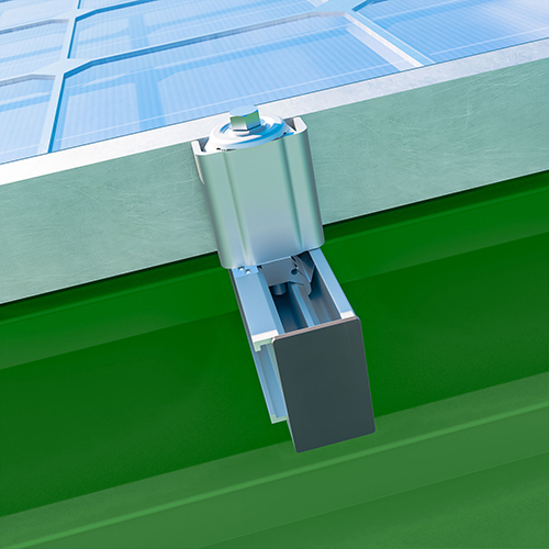
Now let’s talk holding power. Clamps employ a variety of methods to grip the vertical rib on the standing seam roof. Some clamps use one or more setscrews that fasten across the rib. New designs have replaced setscrews with stainless-steel pins that add pressure across the rib with a hex bolt and a special washer. The washer acts as a lock washer, preventing the clamp from loosening under vibration loads due to wind flutter on the roof. The body of the clamp supports the accessory; the setscrews or pin assembly provides the holding force.
The actual holding force can be controlled by tightening the setscrews or pins to a specific torque range developed through testing by each clamp manufacturer. Although there aren’t any solely accepted industry test standards, most manufacturers rely on accredited test laboratories to evaluate their clamps on multiple roof system configurations, including varying material and thickness. This is achieved by taking a section of the roof panel and securing it to a plate mounted on the base of a testing system, such as an Instron. The clamp is then mounted to the roof rib and torqued to the manufacturer’s specification. The movable component of the Instron is attached to the clamp sample. The vertical load required to dislodge the clamp is recorded. That becomes the “ultimate” load.
Most engineers and code officials will require that the ultimate load be divided by a “safety factor” to determine the “design” load to use in the specific project. Typically, the safety factors will be 1.5, 2.0, and, in some critical cases, 3.0. For example, a 24 ga. steel roof panel with the appropriate clamp, installed correctly, will achieve an ultimate vertical load of 1570 lbs. before the clamp slips on the rib. Using a 2.0 safety factor results in a conservative design load of 785 lbs. That load can be used in the equations that determine the number of clamps that would be required to secure an array of PV panels in a given location.
If the roof panel was 0.04″ thick aluminum, the installed torque would likely be reduced to avoid roof panel damage, and the vertical design load would be lower than for the same steel panel. Therefore more clamps would be required to meet the exact design requirements by the building code.
Some applications will require that the manufacturer provide design loads for clamps subjected to vertical loading (perpendicular to the roof surface), lateral loading (loads pushing the clamp along the rib parallel to the roof), and also parallel to the roof but perpendicular to the roof rib.
Manufacturers provide various styles of clamps to fit specific SSMR rib designs. Roof panels are available in several configurations: single lock, double lock, quad lock, Zip Rib, Tee panel, 1.5″ snap-lock, and a wide 1″ snap lock. Contact the clamp manufacturer and let them know what specific panel is on your roof. If you are unsure, a photograph of the panel taken at the eave along with the dimensions measuring from rib to rib and the height of the rib itself may be sufficient to identify the correct clamp for your application. The “right” clamp is the one that the manufacturer tested with the roof panel. Anything else might be sacrificing design load capacity or result in roof damage.
Do’s and Don’ts
• The recommended tool for installation is the drill driver. Impact guns can result in roof panel damage and over-torqued clamps.
• On long runs, 100 feet or more, contact the manufacturer and ask how to compensate for the thermal expansion of the aluminum rails or tubing. Failing to allow for thermal expansion can result in roof damage or system failure.
• Recheck the installed torque after severe wind events.
• Always ask the clamp manufacturer if you have any questions about the clamp or its installation.
• The installer/end-user is responsible for assuring that all engineering studies and data are complete for the installation and that all structural and electrical code requirements have been met.
Remember, the last person on the roof owns it! MR