Understanding Calculations & Patterns for Snow Guard Applications on Metal Rooftops
By Rob Haddock, CEO and Founder of S-5!
Metal roofs are known for their durability, sustainability and versatility. However, metal roofs are slippery and snowpack can suddenly release dumping tons of snow below the eaves in a matter of seconds – endangering building elements, adjacent roofs, landscape, vehicles, property and even worse – pedestrians.
A scientifically tested and engineered snow retention system increases the friction between the roof and the snow, so the buildup of snow and ice on the roof evacuates in a predictable and controlled fashion rather than by a sudden release of sliding snow.
To properly determine the snow guard system for a metal roof, it is critical to:
#1 Understand the math and science that goes into calculating service loads; and
#2 Match the tested load capacity of the snow retention system to the particular roof project.
Calculating the Service Load
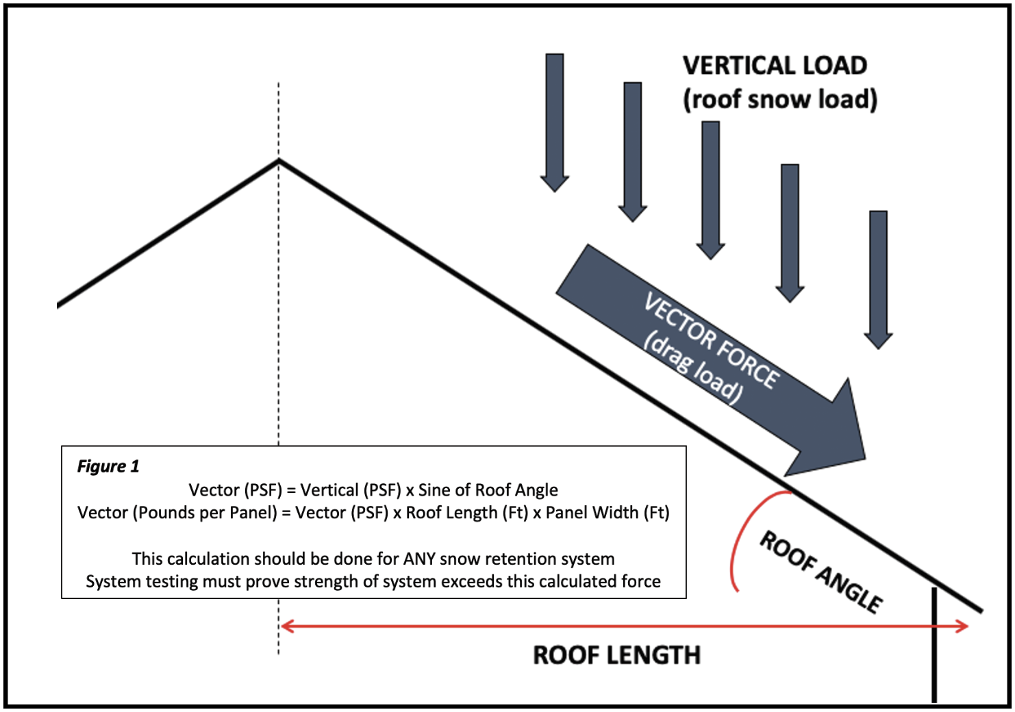
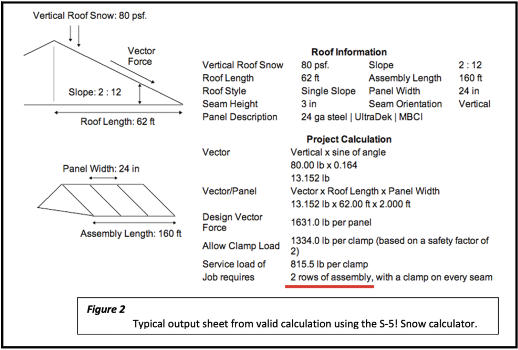
The forces of snow on a rooftop can and should be mathematically calculated… for any snow guard system. (See Figure 1.)
The service loads applied to a snow guard system vary with several site specifics, all of which are known to the design team: 1) the design roof snow load, 2) roof slope, and 3) rafter length (eave-to-ridge). These three factors determine the sliding (vector) force that a system must resist for any roof surface and should be included in specifications requiring an engineered system proving adequate resistance to those forces.
Vector force: The vertical weight of snow is reduced by the sine of the roof angle determining the force parallel to the roof surface that acts on a snow guard. Simply multiply the vertical load (psf) by the sine of the roof angle. The loads for the entire length of each roof panel from eave to ridge are tributary to the snow guard(s) restraining it. That tributary force is determined by multiplying vector force (in psf) by the rafter length (in feet) and the panel width (in feet).
A number of factors should be considered when calculating this force:
1. The roof design snow load (not ground snow) should be used in these calculations. The roof snow (vertical) load is usually reduced from ground snow by some factor, but it may also be increased depending on project-specific variables. This is all dictated by engineering standards.
Caution should be exercised when roof and wall geometries create aerodynamic shade, resulting in drift loads on roof areas. This occurs on roofs adjacent to parapet or other wall conditions that extend above lower rooflines and may increase roof loads significantly. When a lower roof has a roof above not protected by snow guards, the discharge of sliding snow can also cause increased loading (and impact factors) to the lower roof.
A determination must also be made with respect to using uniform or non-uniform loads in design. Building codes should be consulted and appropriate engineering standards and calculations used to determine the actual in-service roof loads in all cases.
2. The coefficient of friction between the roof material and snowbank is so minimal for metal it is not considered in these calculations.
3. Factors of safety (FS) are used when matching the product’s load limitations to the service load. “Ultimate” load is the point at which failure occurs by prudent testing. “Allowable” load is the load used in design to ensure the failure point is never reached in service. The appropriate FS is subject to designer/engineer discretion. The Metal Construction Association (MCA) recommends a FS no less than 2.0 for mechanically attached snow guards.
There are no ASTM standards for the use or testing of snow guards, so the buyer must consider the repetition, appropriateness and credibility of any testing presented to validate the frequency of placement as well as expected performance life (which should be equivalent to the roof life). After determining the service loads to be resisted and matching them to the snow retention system, it is important to determine population and placement for the specific metal roof. This is one more step of simple math: divide the tested allowable load of the device into the service load to determine the required frequency (population) and spacing of the device(s) for any given project. (See Figure 2.)
Snow Retention System Design Considerations
Snow Retention Population and Placement
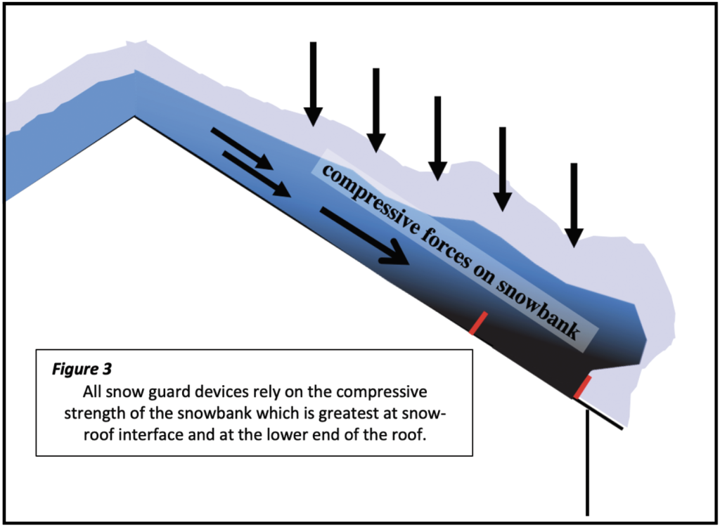
Snowbanks typically accumulate and densify in a cross-sectional wedge pattern. All snow guards rely on the snow’s own compressive strength to restrain its movement. Gravitational forces compress the snowbank the most at its interface with the roof surface, especially toward its lower (eave) end—so this is where compressive strength is greatest. (See Figure 3.)
The interface of snow retention devices at this location has proven to be strongly preferred worldwide and considered to be most effective. Because the compressive strength is so great at the base of the snowbank, snow guard devices only a few inches in height have proven to be successful even when snowbanks are many feet deep.
System Design
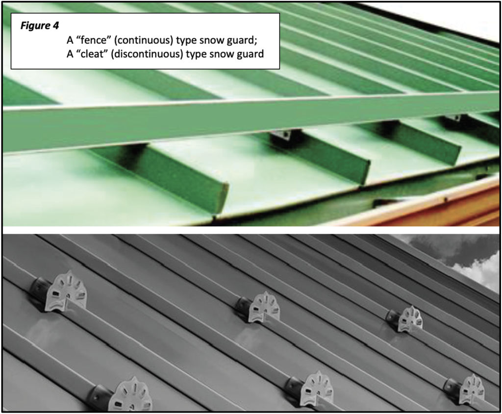
Two snow guard concepts are quite common. One utilizes continuous horizontal components, assembled laterally across the roof in the style of a “fence.” Such assemblies are usually installed at or near the eaves. Depending on specific job conditions and load-to-failure characteristics of the devices, they may also be repeated in parallel rows up the slope of the roof, but with greater concentration near the eave area.
The other design consists of small, discontinuous individual units used as “cleats,” generally spot-located at or near the eave or repeated in a pattern progressing up the slope of the roof, again with a greater concentration near the eaves. This style also relies upon the shear strength within a snow bank to “bridge” between the individual units.
Both styles of snow guards (fence and cleat) have demonstrated satisfactory performance when tested, engineered and installed properly and adequately.
Additional Considerations
Aside from adequate testing for holding capacity, other design considerations include verifying metals’ compatibility, matching corrosion resistance of the device with that of the panel material, and color matching. The objective is serviceability that lasts as long as the roof.
More information, videos and webinars on this topic are available at www.s-5.com and www.metalconstruction.org. MR
About the Author: S-5! CEO and Founder Rob Haddock, is a former contractor, award-winning roof-forensics expert, author, lecturer and building envelope scientist who has worked in various aspects of metal roofing for five decades.

Sign Up For A Free Subscription
Anyone who is involved in the construction trade is welcome to sign up for a free print or digital subscription to Metal Roofing Magazine, which has been advancing the metal roofing industry since 2001. This go-to resource for metal roofing professionals is published 7 times per year.